
1: Simple LED
This is the first build because it teaches the main idea of a circuit: electricity needs a complete path.
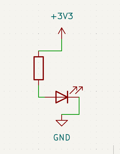
In this project, you will build the simplest possible circuit: power goes out from 3V3, through a resistor and LED, and returns to GND.
Along the way you will practice:
- what it means for a circuit to have a complete path
- why an LED must face the right direction (long leg
+, short leg-) - why a resistor protects the LED
Learn more (optional):
Goal
Make one LED turn on.
Parts you need
- 1 LED
- 1 resistor
- jumper wires
- breadboard
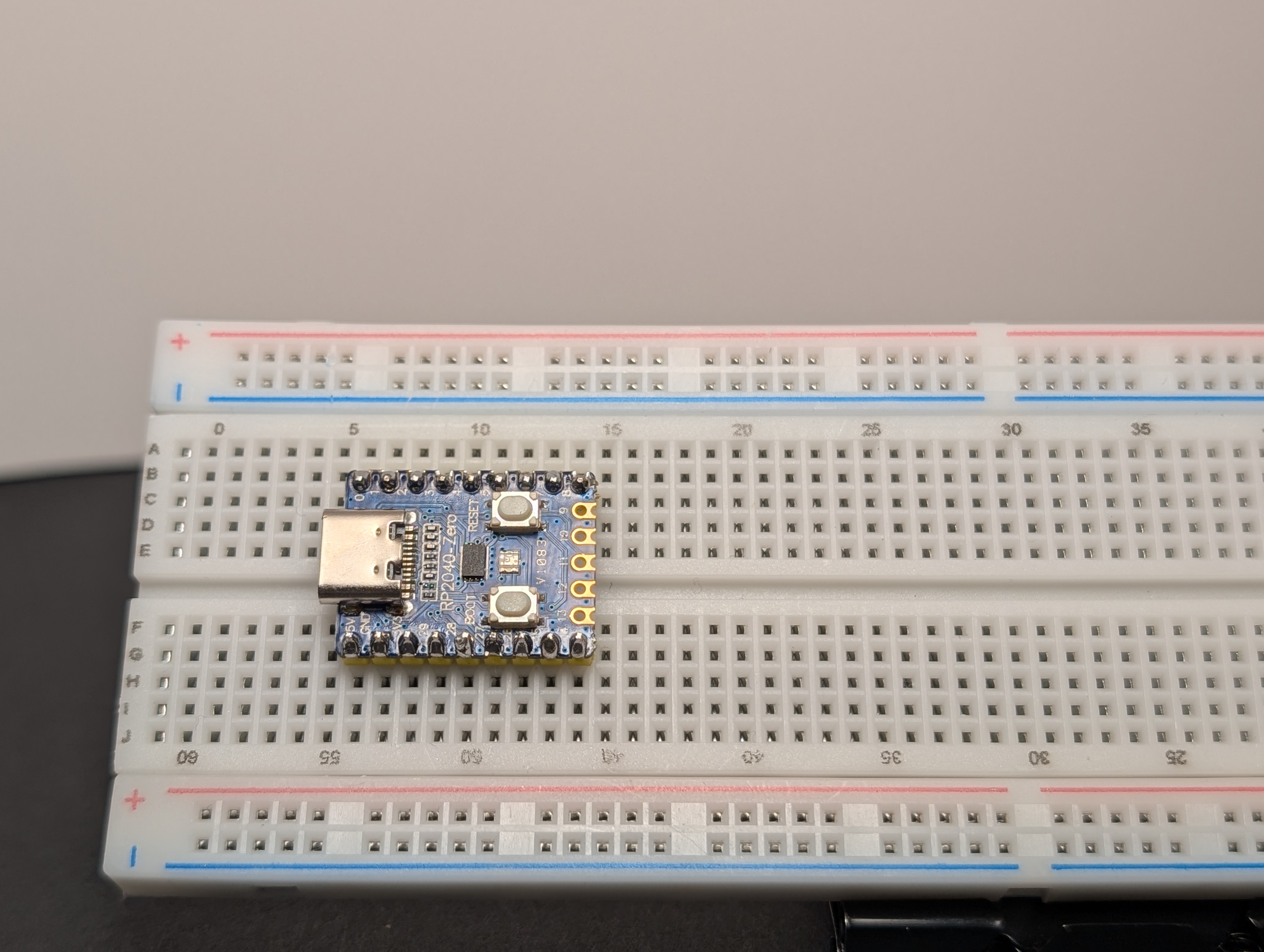
- RP2040-Zero
Build idea
You are making a path like this:
3V3 -> resistor -> LED -> GND
That means power leaves the 3V3 pin, goes through the resistor, passes through the LED, and returns to GND.
Build steps
Try each step, then check your work with the blurred photos below. Did you connect it the way you meant to?
Important: choose the right resistor
Your kit has 150Ω and 100Ω resistors.
- For a red or yellow LED, use 150Ω
- For a green, blue, or white LED, use 100Ω
Using the wrong resistor can damage an LED.
- Place the RP2040-Zero into the breadboard.
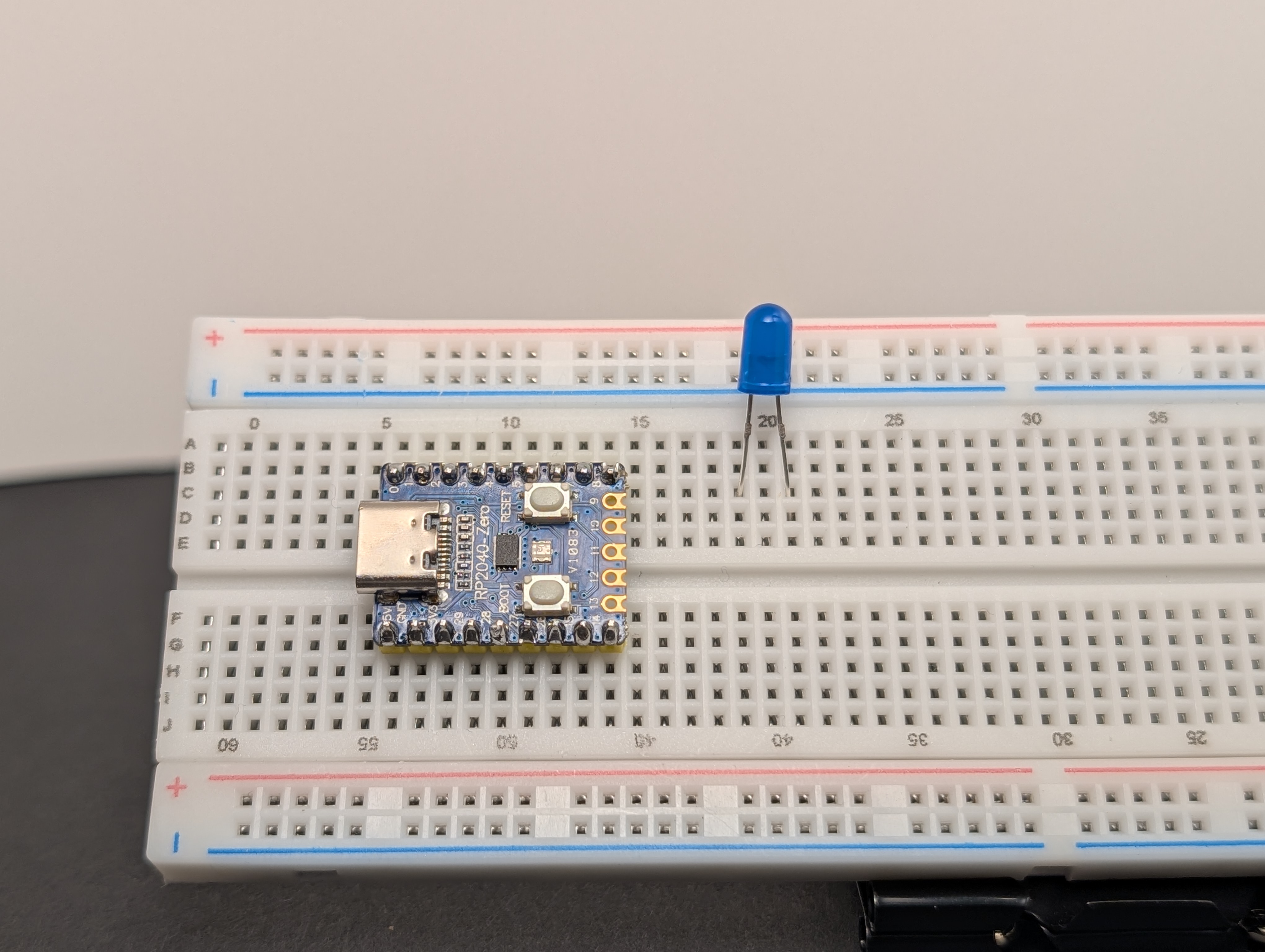
- Place the LED on the breadboard so the two legs are in different rows.
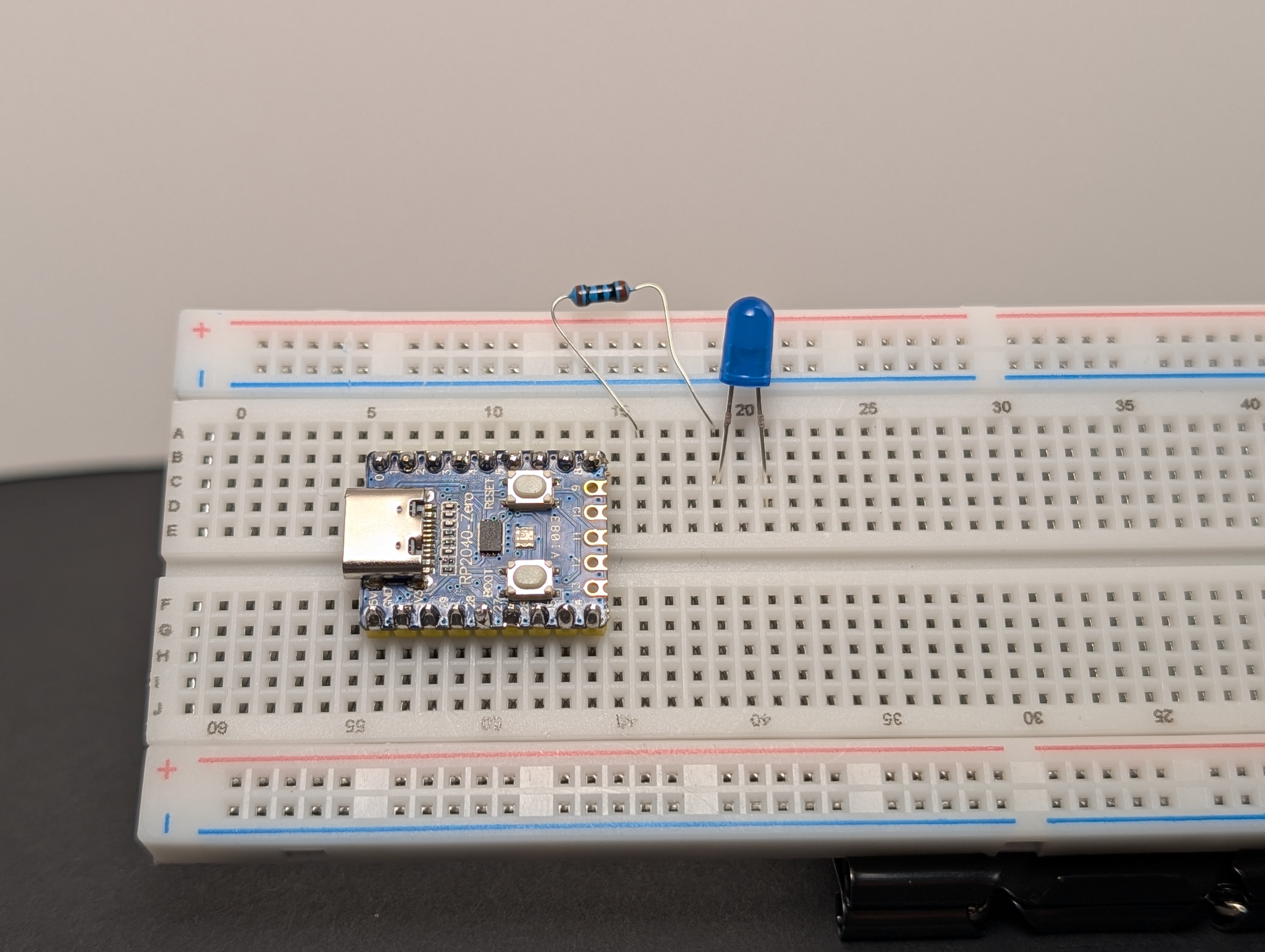
- Put a resistor in series with the LED, connected to the long leg (
+).
- Using a jumper wire, connect the resistor side to
3V3.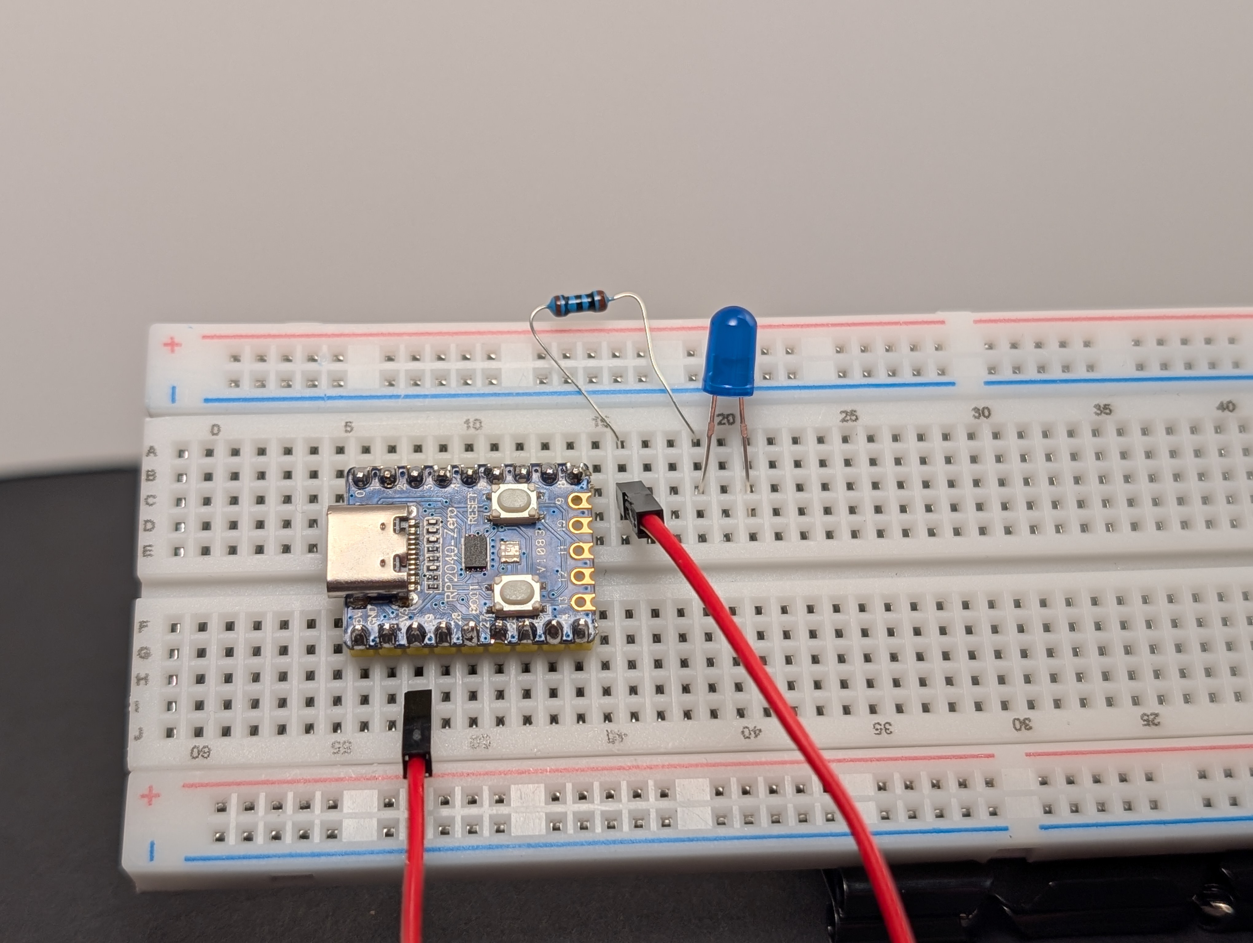
- Using a jumper wire, connect the short leg (
-) of the LED toGND.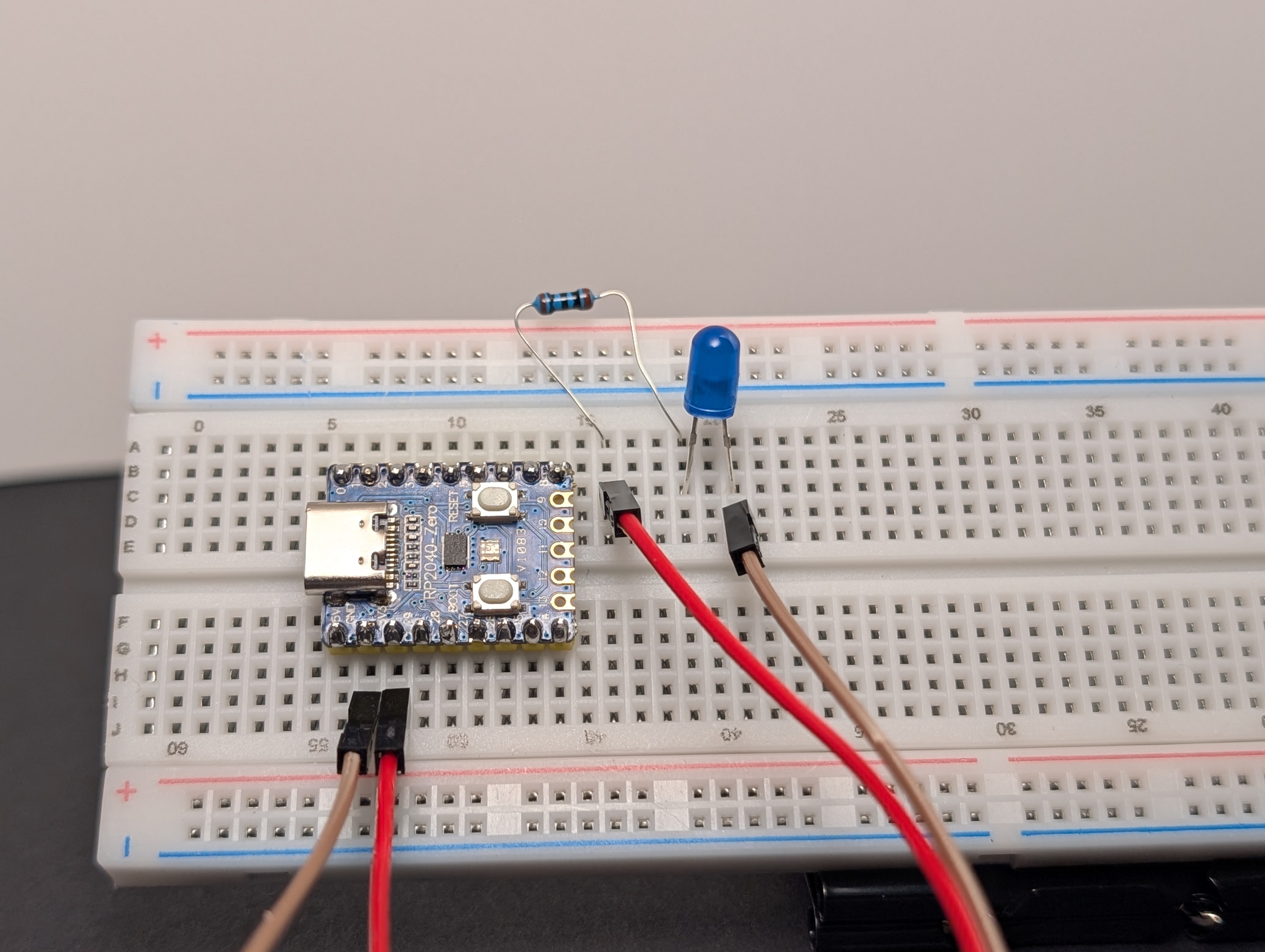
- Plug the board into USB.
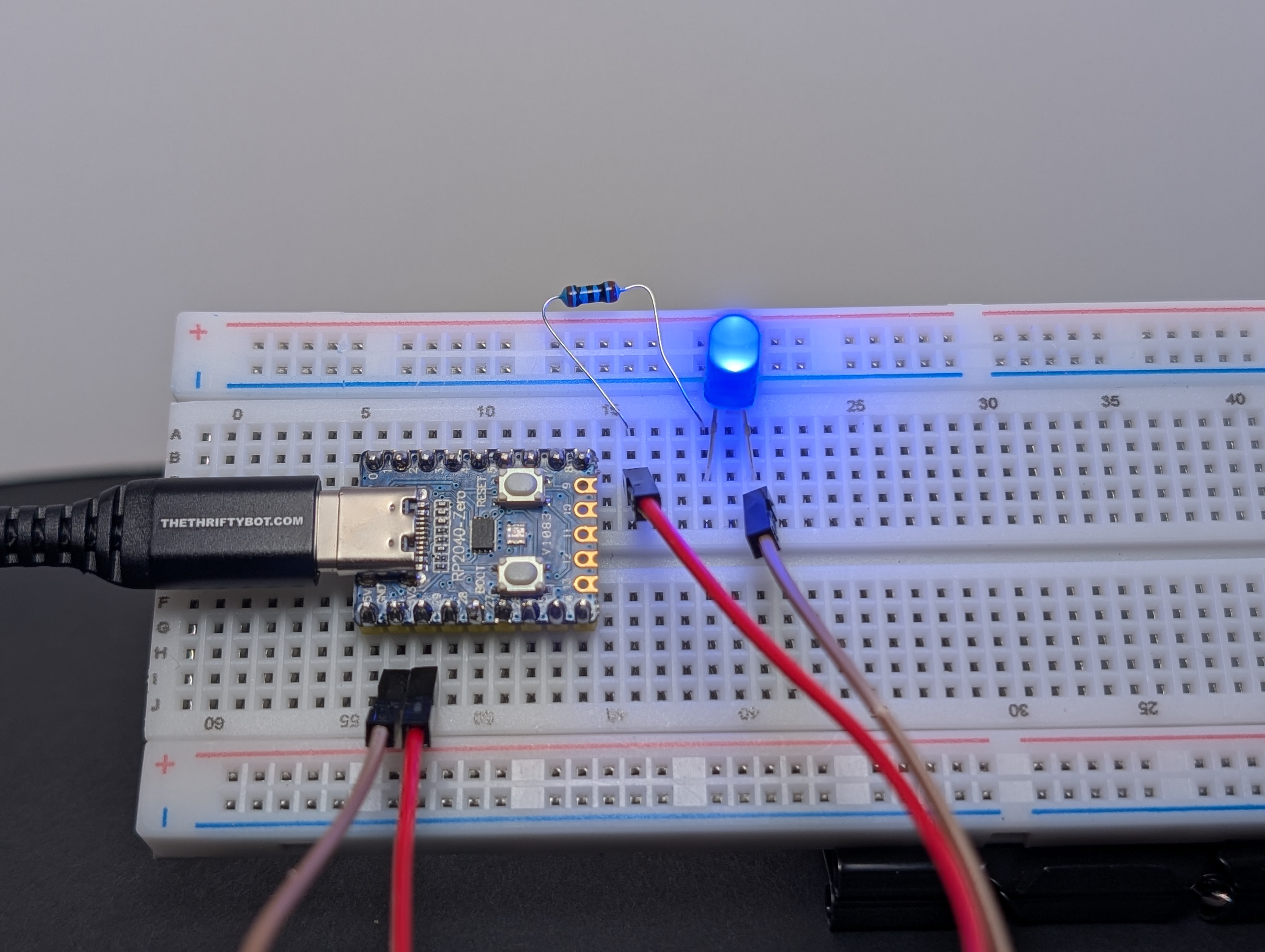
If everything is connected correctly, the LED should light up.
What to notice
- The LED only works when it is facing the correct direction.
- The resistor helps keep the LED safe.
- If the path is broken anywhere, the LED turns off.
If it does not work
Check these first:
- Is the LED backward?
- Is the resistor really in the same path as the LED?
- Is one side connected to
3V3and the other toGND? - Are the LED legs in different rows?
Try this next
Swap the LED for a different color and see what changes.