
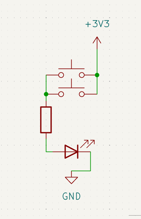
3: OR Gate with Two Buttons
This circuit is a simple OR gate made with two buttons.
If you want the fuller explanation first, see OR gate in Electricity.
An OR gate is a kind of logic gate. A logic gate is a circuit that turns an output on or off based on one or more inputs.
In this circuit, the two buttons are the inputs. The LED is the output. If either button can complete a path to power, the LED turns on.
Learn more (optional):
Goal
Make the LED turn on if either button is pressed.
Parts you need
- 1 LED
- 1 resistor
- 2 pushbuttons
- jumper wires
- breadboard
- RP2040-Zero
Important: choose the right resistor
Your kit has 150Ω and 100Ω resistors.
- For a red or yellow LED, use 150Ω
- For a green, blue, or white LED, use 100Ω
Using the wrong resistor can damage an LED.
Build idea
An OR gate turns the output on when either input can complete the path.
In this circuit, each button is its own input.
You will make two possible paths from 3V3 to the LED.
If button A is pressed, the LED gets power.
If button B is pressed, the LED also gets power.
If both are pressed, that still works too, which is exactly how an OR gate behaves.
Build steps
Try each step, then check your work with the blurred photos below. Did you connect it the way you meant to?
- Build circuit 2: LED with Button.

- Unplug the USB, if it's still connected.
- Add a second button, making sure it bridges the center of the breadboard.

- Using a jumper wire, connect one side of both buttons to
3V3.
- Using a jumper wire, connect the other side of both buttons to the same row that leads into the resistor and LED.

- Make sure the LED is still connected to
GND. - Plug in the USB, then test each button one at a time, then both at once.


What to notice
- The two buttons are in parallel.
- Parallel means there is more than one path.
- Either path can make the LED light, so this circuit acts like an OR gate.
Try this next
Can you add a third button?