
5: Blink with Code
Now the RP2040-Zero will control the LED instead of your finger.
In this project, the LED is still a normal circuit, but the “switch” is controlled by code. A GPIO pin can act like an output switch: when your code sets it HIGH, current can flow and the LED can turn on.
Coding ideas you will use:
- a variable to store the pin number (
LED_GPIO) - an infinite loop (
while True) so the board keeps running - timing (
time.sleep) to control how fast it blinks
Learn more (optional):
Goal
Write code that makes an LED blink on and off.
Parts you need
- 1 LED
- 1 resistor
- jumper wires
- breadboard
- RP2040-Zero
Important: choose the right resistor
Your kit has 150Ω and 100Ω resistors.
- For a red or yellow LED, use 150Ω
- For a green, blue, or white LED, use 100Ω
Using the wrong resistor can damage an LED.
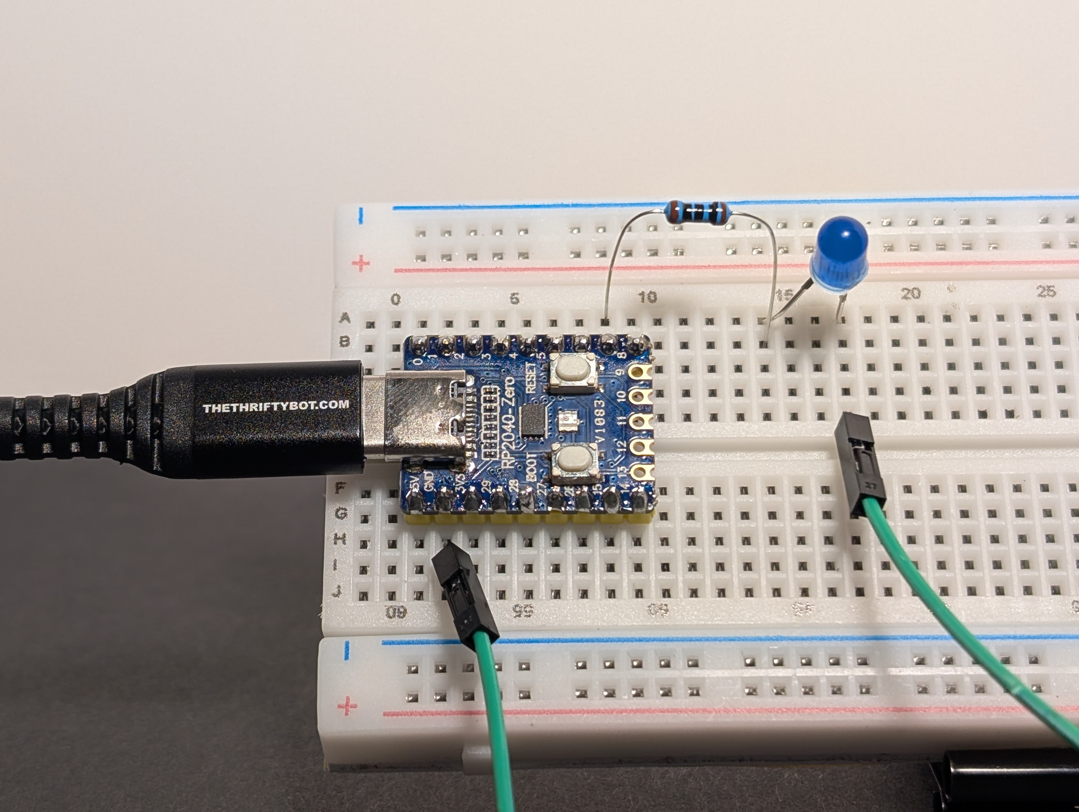
Wiring idea
Build it first, then compare your setup to the picture. Did you connect each part to the pin you meant to use?
Use one GPIO pin to control the LED.
Example pin: GP7 (GPIO 7).
Hint
Build circuit 1: Simple LED, but connect the LED to a GPIO pin instead of 3V3.
Example path:
GPIO -> resistor -> LED -> GND
Code
Pin reminder
Wired your LED to a different GPIO pin? Update LED_GPIO in the code below to match your wiring.
import machine
import time

LED_GPIO = 7

# Set up the pin as an output
led = machine.Pin(LED_GPIO, machine.Pin.OUT)

print("Blinking LED on GPIO", LED_GPIO, "... Press Ctrl+C to stop.")

while True:
    led.value(1)    # Turn LED on
    time.sleep(0.5) # Wait 500ms
    led.value(0)    # Turn LED off
    time.sleep(0.5) # Wait 500ms
Arduino Code Coming Soon
What the code does
machine.Pin(LED_GPIO, machine.Pin.OUT)tells the board to use that GPIO pin as an outputled.value(1)turns the pin onled.value(0)turns the pin offtime.sleep(0.5)waits half a second
Try this
Change the timing values.
- What happens at
0.1seconds? - What happens at
1second?
Debug tip
If the code runs but the LED does not blink, check that the jumper wire is really connected to the same GPIO pin number used in the code.