
2: LED with Button
Now you will add a button so the LED only turns on when you press it.
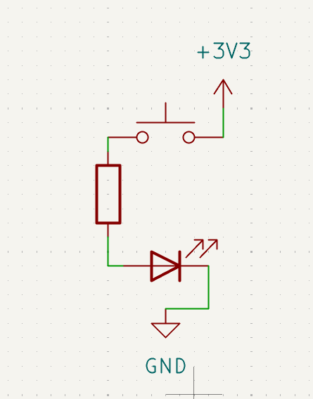
This is the same basic LED circuit as circuit 1, but with a switch added. A pushbutton is a temporary switch: when you press it, it connects two points and completes the path.
Along the way you will practice:
- what a switch does (open path vs. closed path)
- how parts in series must all be connected for current to flow
Learn more (optional):
Goal
Make the LED light only while the button is pressed.
Parts you need
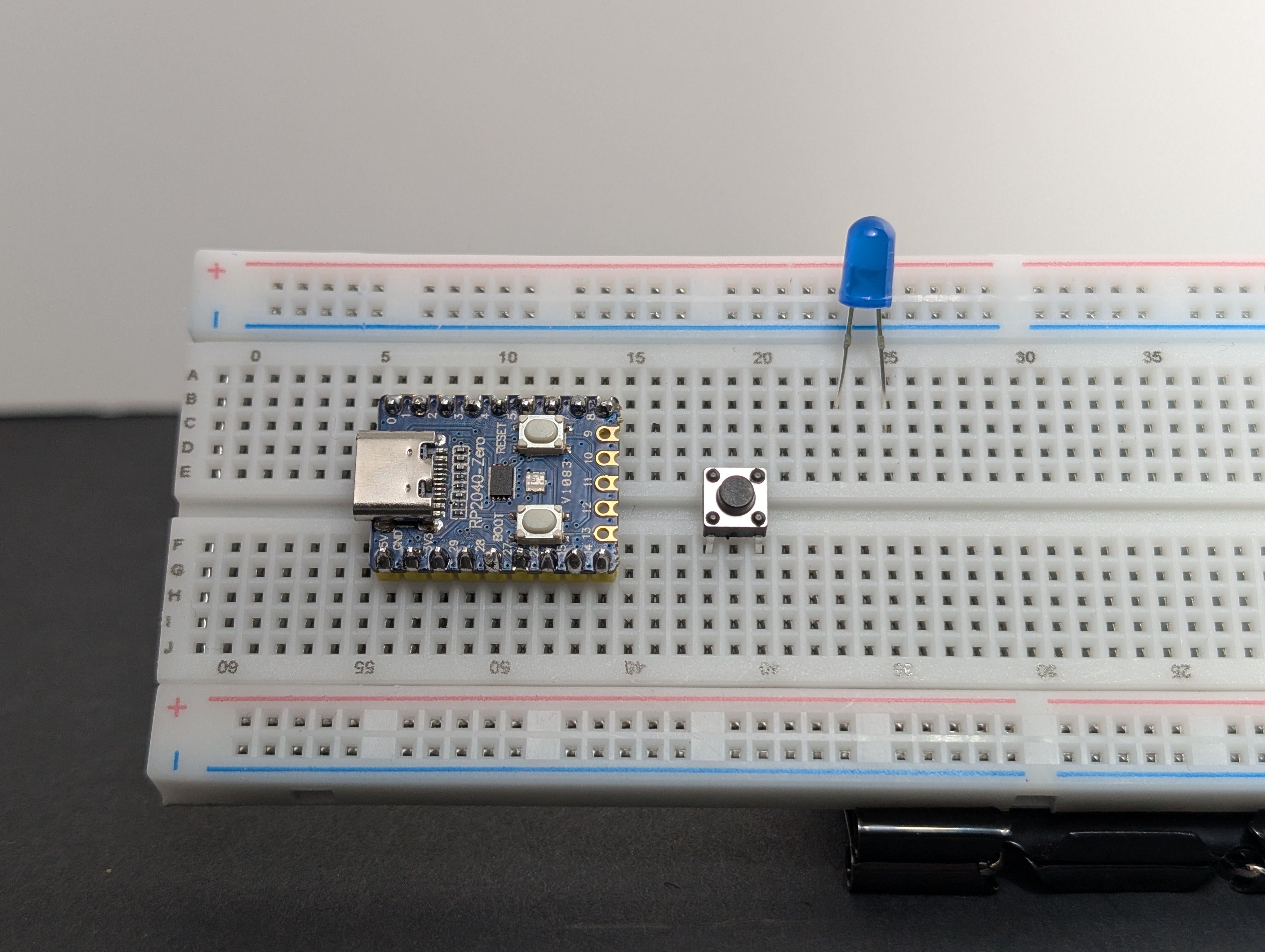
- 1 LED
- 1 resistor
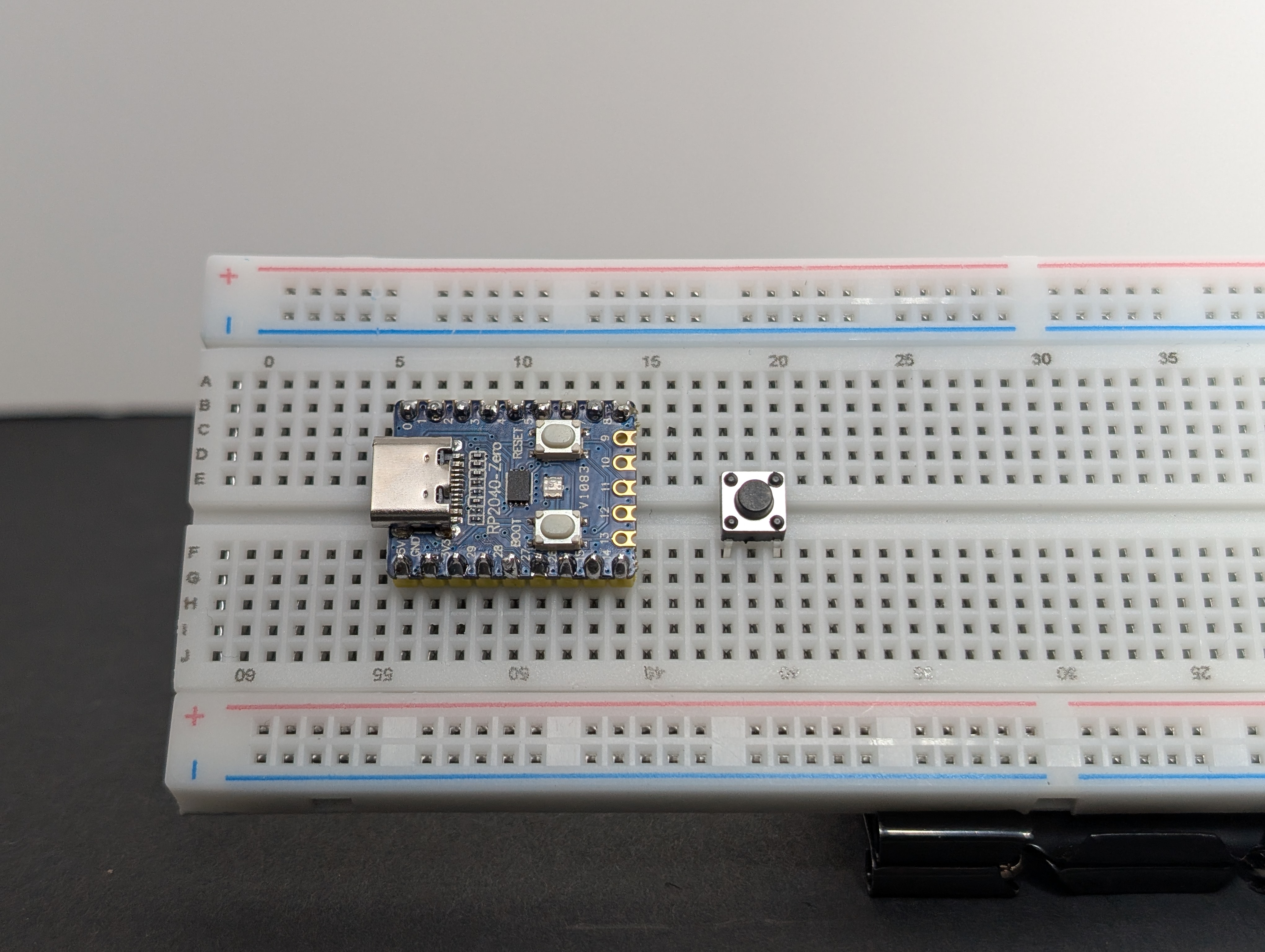
- 1 pushbutton
- jumper wires
- breadboard
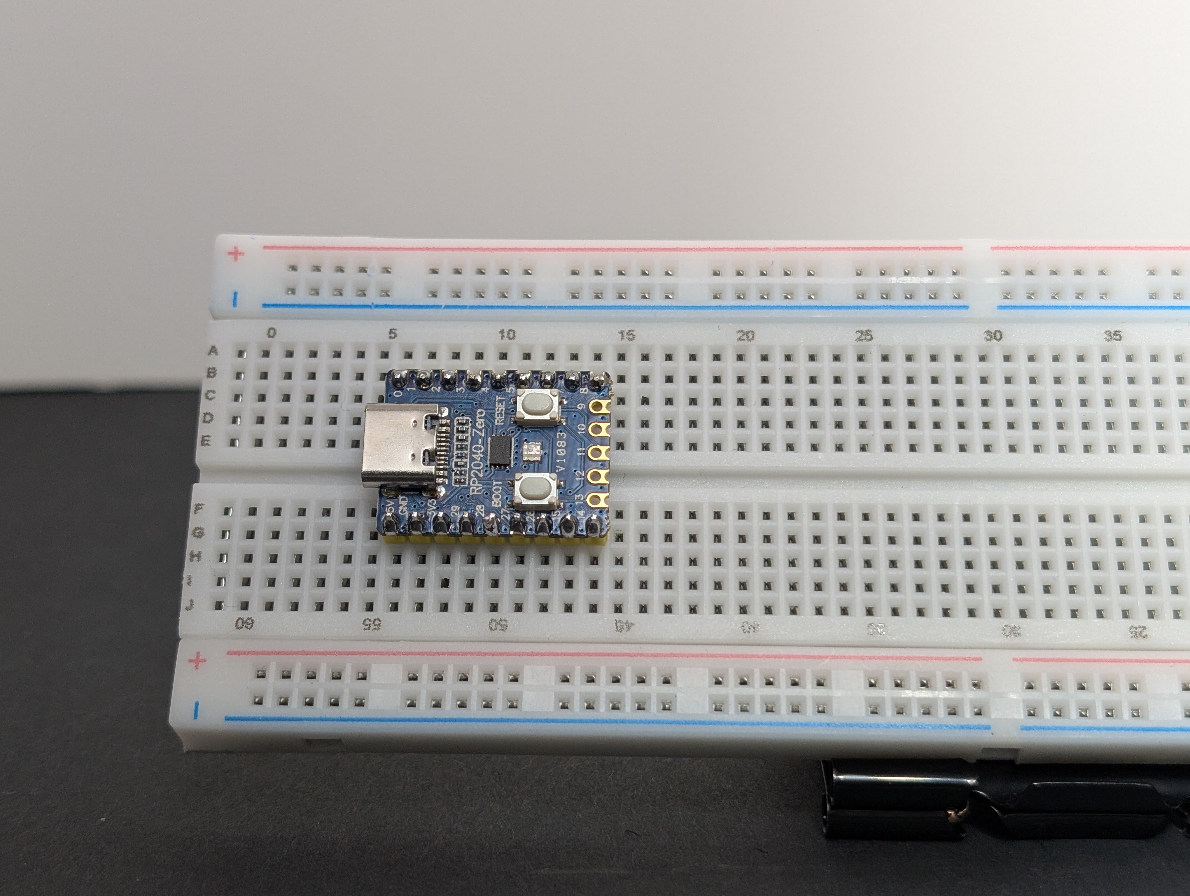
- RP2040-Zero
Build idea
You are adding a switch into the path:
3V3 -> button -> resistor -> LED -> GND
When the button is not pressed, the path is open.
When the button is pressed, the path closes and the LED can light.
Build steps
Try each step, then check your work with the blurred photos below. Did you connect it the way you meant to?
Important: choose the right resistor
Your kit has 150Ω and 100Ω resistors.
- For a red or yellow LED, use 150Ω
- For a green, blue, or white LED, use 100Ω
Using the wrong resistor can damage an LED.
- Place the RP2040-Zero into the breadboard.
- Place the pushbutton so it bridges the center gap of the breadboard.
- Place the LED so its legs are in different rows.
- Put the resistor between one side of the button and the long leg (
+) of the LED (in series).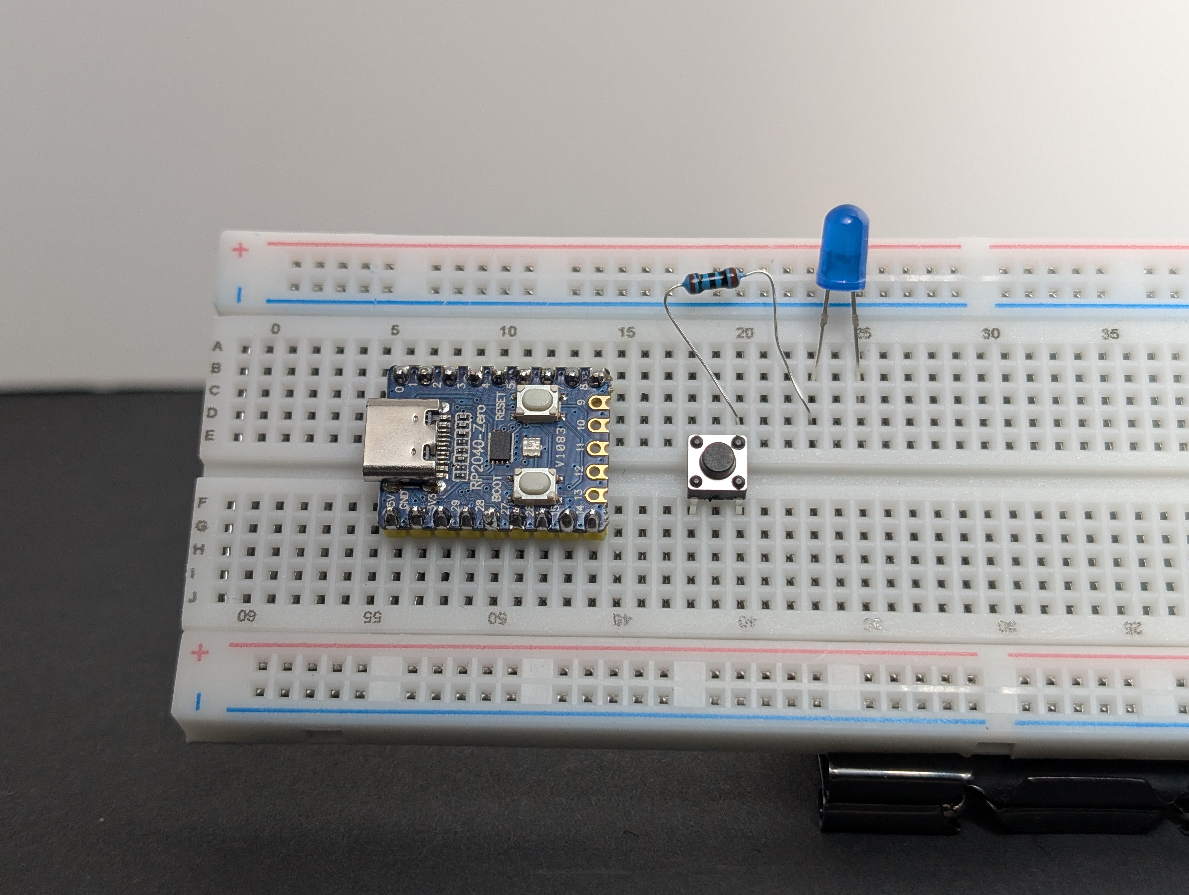
- Using a jumper wire, connect
3V3to the same row as the button leg that shares a row with the resistor.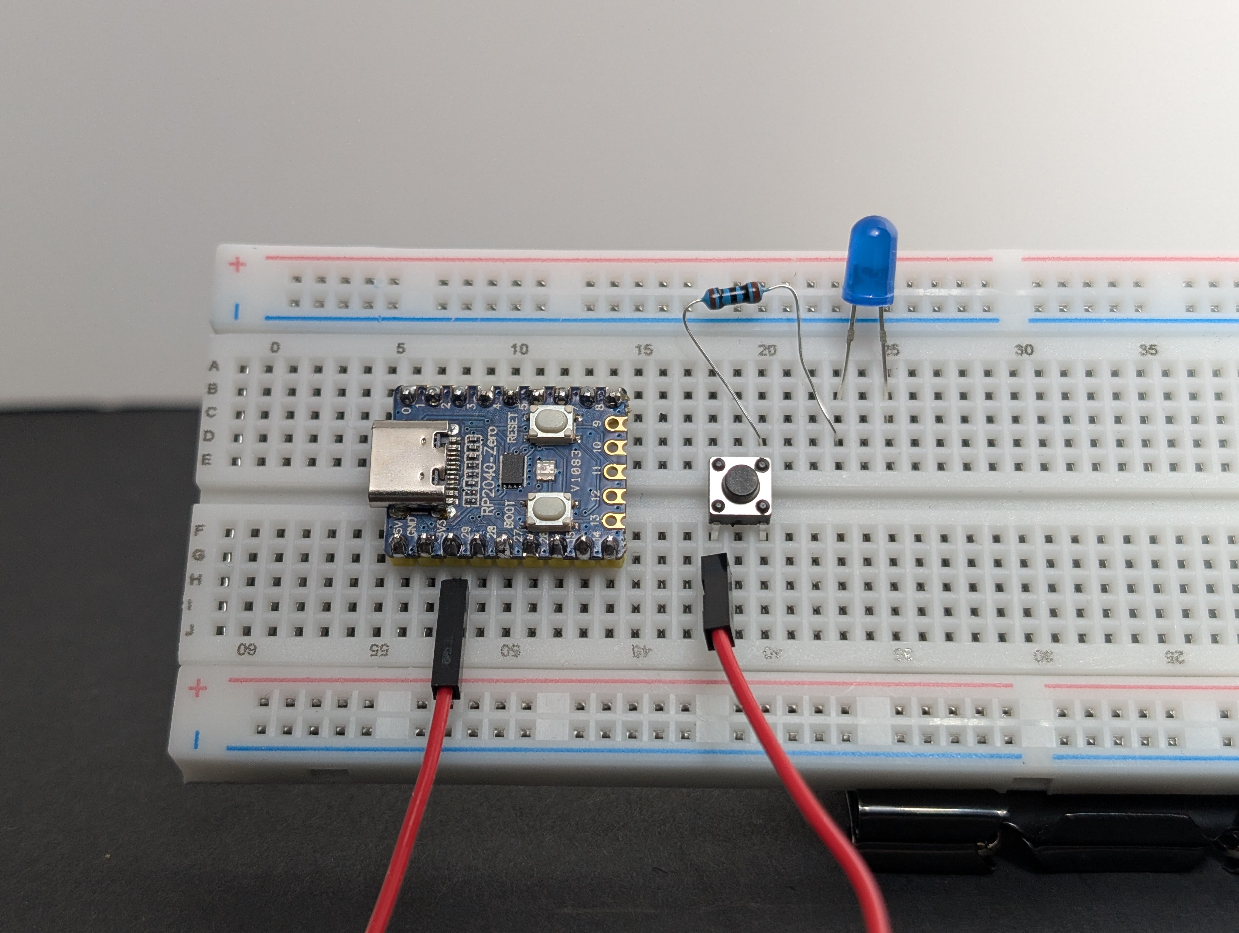
- Using a jumper wire, connect the short leg (
-) of the LED toGND.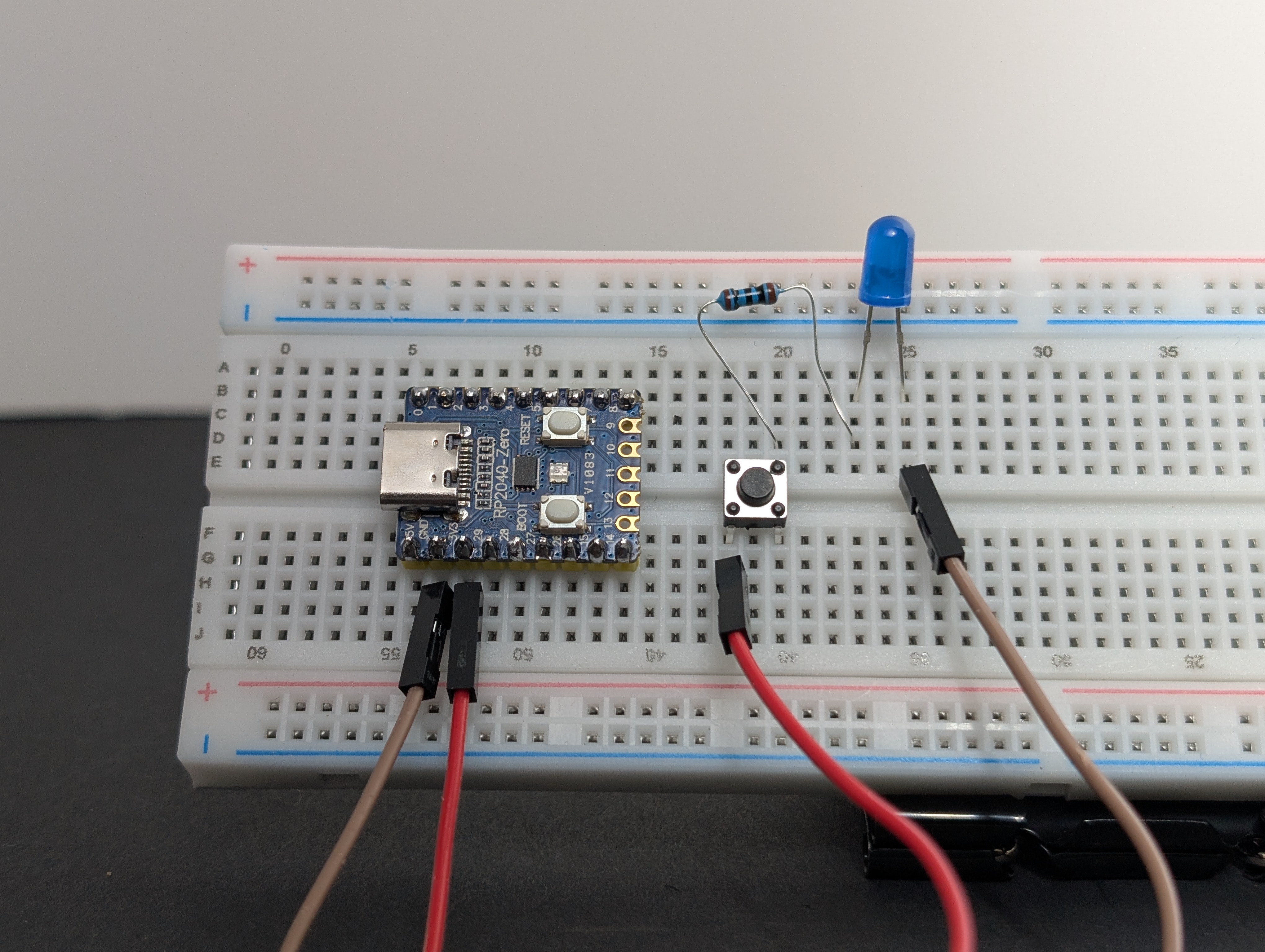
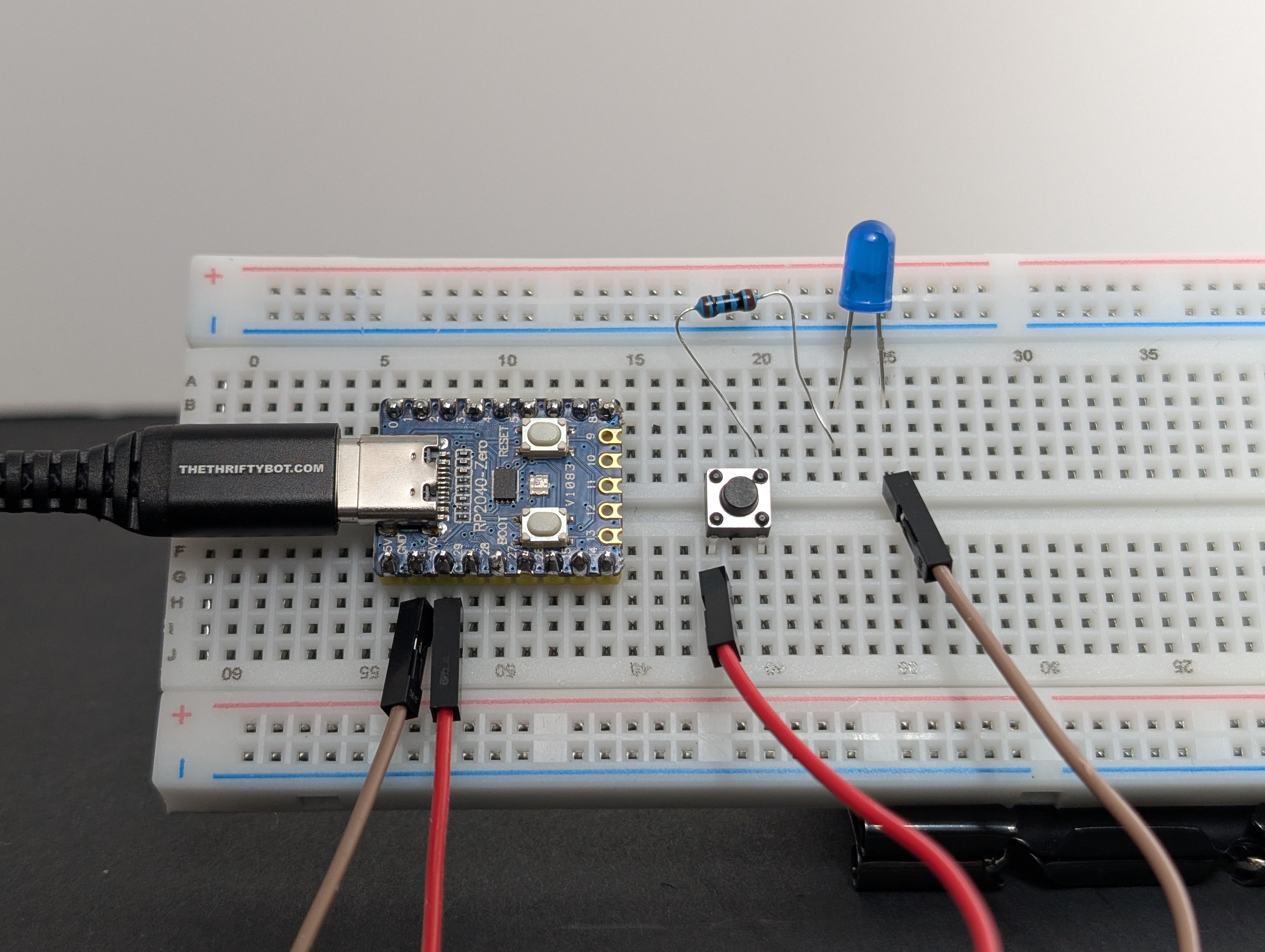
- Plug the board into USB, then test the button.
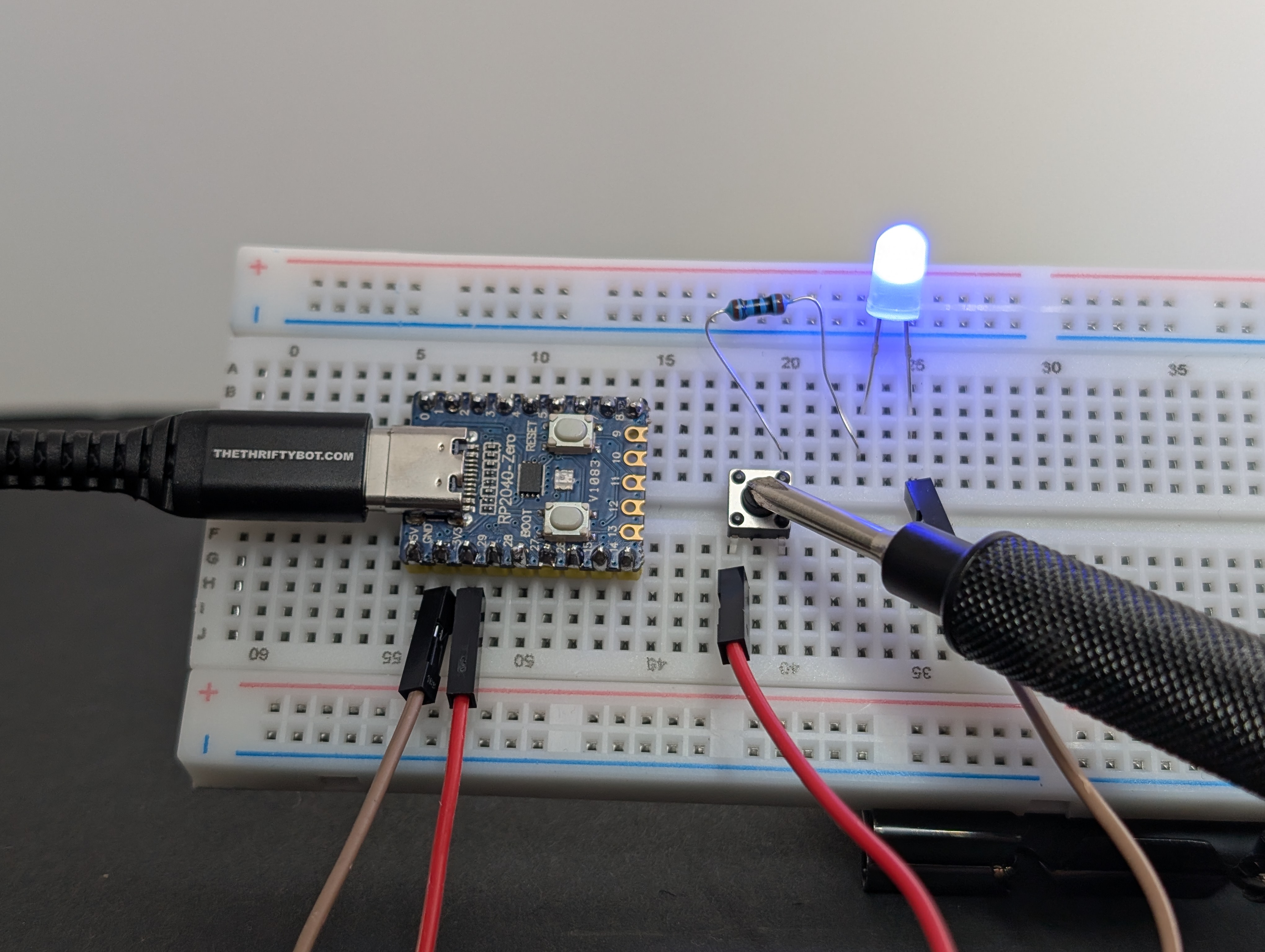
The LED should light only when the button is pressed.
What to notice
- The button is acting like a temporary bridge.
- If the button is turned the wrong way on the breadboard, the circuit may stay open all the time.
- This is still a circuit, just one you control with your finger.
Try this next
What do the different pins on the pushbutton do, if you connect the resistor or power to it?